Reading Structural Steel Drawings Made Easy: Symbols, Plans, and Lift Preparation
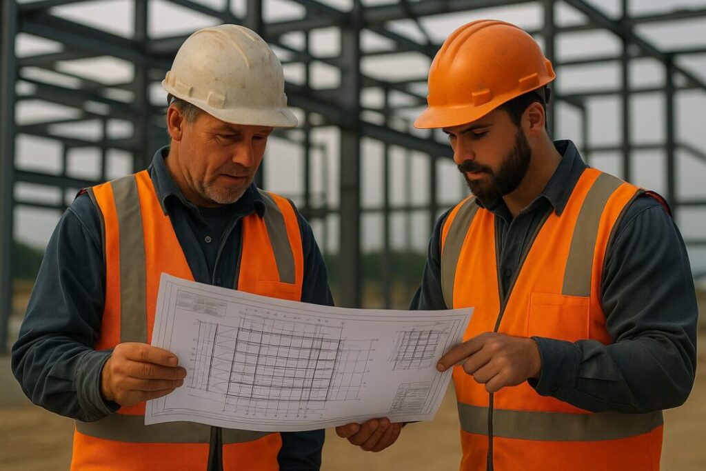
Structural steel drawings are the backbone of modern construction projects. They serve as the roadmap for fabricators, riggers, and engineers to transform a design into a safe, functional structure. Yet, many professionals—even those with years of experience—struggle to interpret and plan effectively from these detailed documents. Misreading a symbol or overlooking a note can lead to costly mistakes, project delays, or even safety hazards.
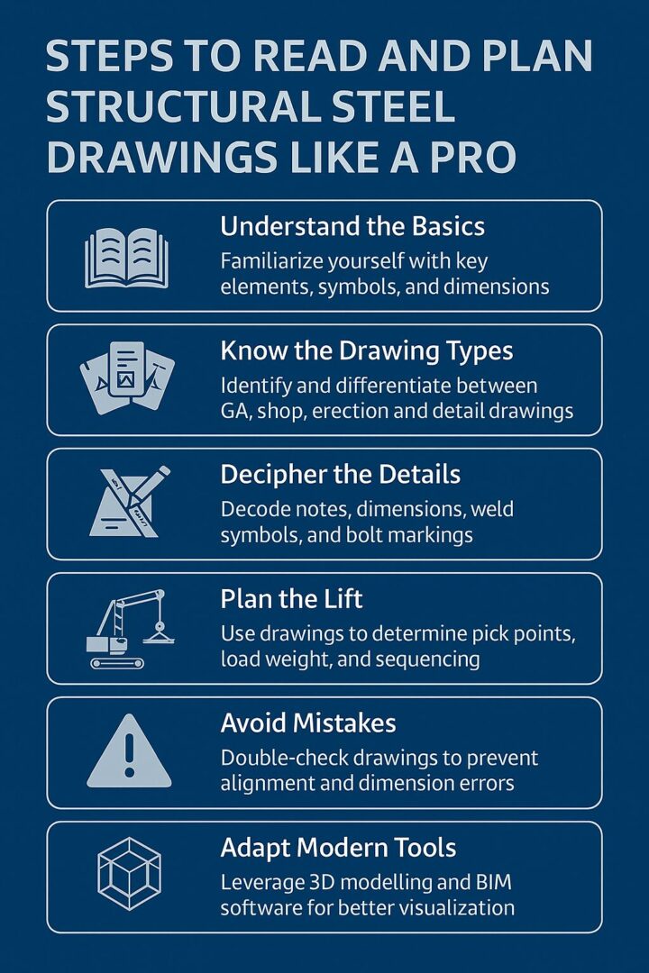
This guide will walk you through how to read and plan structural steel drawings like a pro, from understanding symbols and drawing types to creating efficient lift and erection plans. Whether you’re a project manager, junior engineer, or rigger aiming to improve your skills, this step-by-step approach will help you master the process.
Understanding Structural Steel Drawings
Structural steel drawings are highly detailed diagrams that outline every steel component required for a construction project. They include dimensions, materials, connection details, and assembly instructions, ensuring every beam, column, and bolt is accurately fabricated and installed.
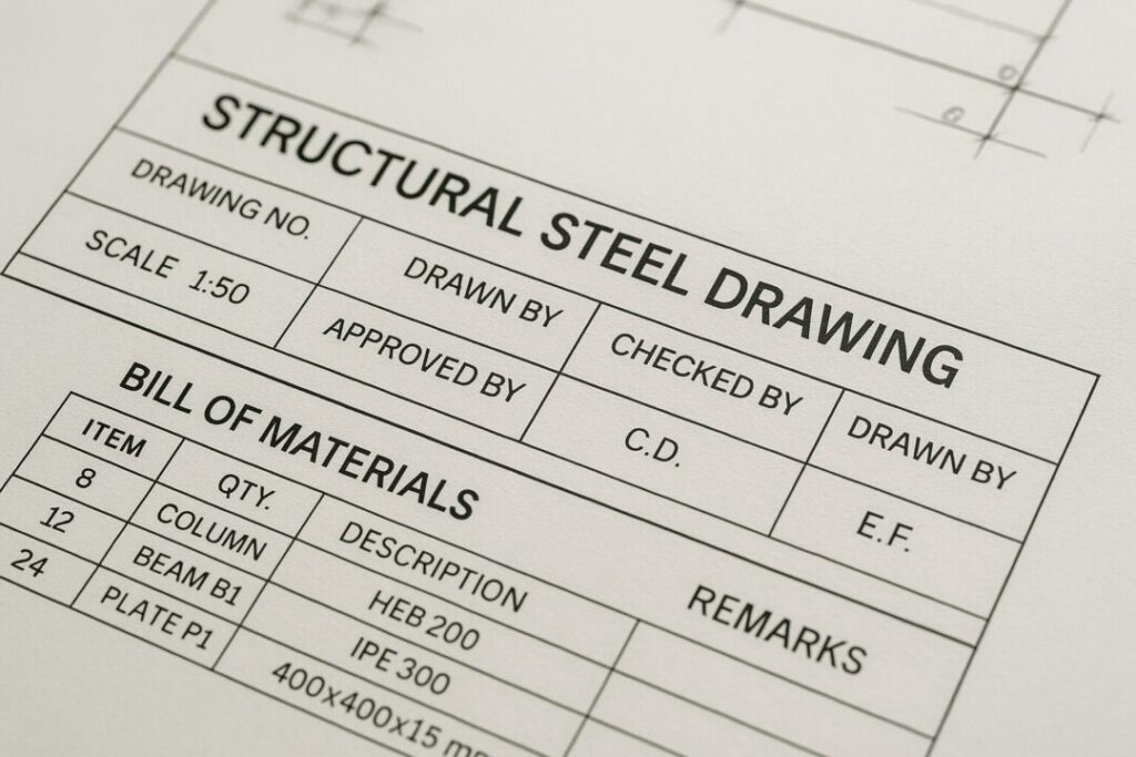
Key Elements of a Steel Drawing
- Title Block: Lists project name, location, date, drawing number, scale, and revision history.
- Bill of Materials (BOM): Itemises every steel component, showing part numbers, quantities, lengths, and weights.
- Symbols and Abbreviations: Indicate weld types, bolt sizes, centre lines, hidden edges, and other key specifications.
- Revision Clouds: Highlight updates or changes to avoid using outdated information.
Tip: Always verify you’re using the latest drawing revision before starting any work.
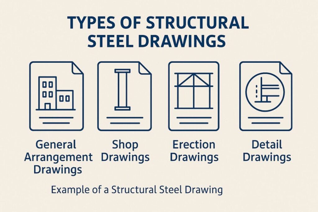
Types of Structural Steel Drawings
Each drawing type serves a different purpose. Understanding these will help you plan efficiently and avoid errors.
- General Arrangement (GA) Drawings: Show the overall layout of the structure, including positioning of beams, columns, and connections.
- Shop Drawings: Provide fabrication details for each component, such as hole patterns, plate thickness, and weld locations.
- Erection Drawings: Focus on the order and method of assembling components onsite.
- Detail Drawings: Zoom in on specific connections, bracings, or complex parts requiring precise installation.
Pro Tip: A seasoned rigger or site manager will cross-reference GA and erection drawings to pre-plan the lifting sequence and avoid clashes during assembly.
Reading Symbols, Notes, and Dimensions
Structural drawings are like a language. Learning to read their “grammar” ensures accuracy on site.
- Lines:
- Solid: Visible edges
- Dashed: Hidden edges or components not in current view
- Chain: Centre lines or symmetry indicators
- Solid: Visible edges
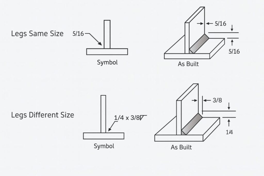
- Weld Symbols: Define type, size, and location of welds.
- Bolting Notes: Specify bolt grade, size, and torque requirements.
- Levels and Elevations: Indicate vertical positioning relative to a benchmark point.
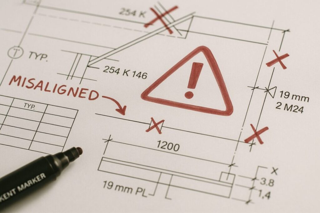
Mistake to Avoid: Misreading symbols can result in improper connections that compromise structural integrity.
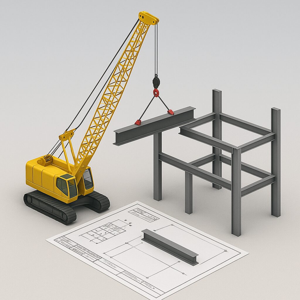
Using Drawings for Planning Lifts
Steel rigging and erection rely heavily on well-planned lifting operations. A drawing isn’t just for measurements—it’s a blueprint for safe lifting.
Steps to Create a Lift Plan
- Review the BOM: Note component weights and centre of gravity.
- Identify Pick Points: Check where slings and shackles can safely attach without damaging steel members.
- Assess Crane Reach and Capacity: Use GA drawings to determine optimal crane positioning.
- Plan Sequencing: Decide lifting order to avoid double handling and ensure structural stability during partial erection.
- Include Safety Margins: Factor in wind, ground conditions, and restricted site access.
By combining information from shop and erection drawings, you can predict potential conflicts and plan lifts that minimise risk.
Avoiding Common Mistakes
Even experienced professionals can make errors when reading or using steel drawings. The most frequent mistakes include:
- Using outdated revisions
- Ignoring welding or bolting specifications
- Overlooking load weights during lift planning
- Misinterpreting camber or tolerances
- Failing to coordinate with other trades
Solution: Always cross-check drawings, consult engineers for clarification, and hold pre-lift meetings with the crew to review plans.
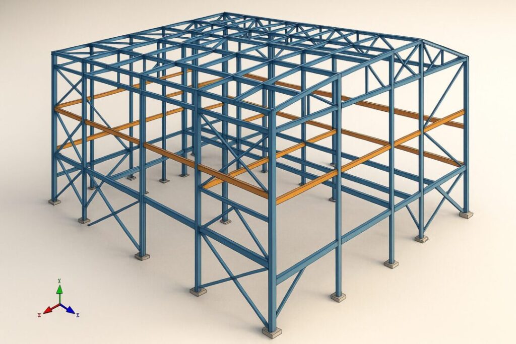
Leveraging BIM and 3D Modelling
Modern tools like Tekla Structures and Navisworks allow you to view steel models in 3D before construction begins. These tools help:
- Detect clashes between components or trades early.
- Generate lift simulations for complex assemblies.
- Provide visual guidance to riggers and crane operators.
Industry Insight: Many leading Australian steel contractors now require BIM-based erection plans to enhance precision and reduce onsite risks.
Australian Standards and Compliance
In Australia, structural steel projects follow strict codes:
- AS 4100 – Steel Structures: Sets out design, fabrication, and erection requirements.
- Safe Work Australia Guidelines: Outline rigging, lifting, and working-at-height safety standards.
Ensuring drawings and lift plans comply with these standards protects both workers and the finished structure.
Final Checklist for Reading and Planning Like a Pro
- ✅ Use the latest revision of every drawing.
- ✅ Understand all symbols, notes, and abbreviations before starting.
- ✅ Cross-reference GA, shop, and erection drawings.
- ✅ Plan lifts with weight, pick points, and sequencing in mind.
- ✅ Coordinate closely with engineers, riggers, and crane operators.
- ✅ Follow AS 4100 and WHS guidelines at every step.
Conclusion
Reading and planning from structural steel drawings is a critical skill that separates average project execution from exceptional, safe, and efficient builds. By learning to decode symbols, use multiple drawing types effectively, and develop proactive lift plans, you’ll not only avoid costly mistakes but also elevate the quality of every steel project you handle.
At Hard Bakka Rigging, we specialise in precision steel rigging services across NSW, backed by 30+ years of collective expertise. Our team works hand-in-hand with engineers, fabricators, and contractors to turn drawings into reality—safely, accurately, and on schedule.
📞 Call Bill Bakka: +61 415 878 744
📩 Email: sales@hardbakkarigging.com.au
🌐 Visit: www.hardbakkarigging.com.au.com.au!